Engineering Logic Diagram
Engineering logic diagrams Logic gates with diagram circuit – ahirlabs Truth logic gates tables table diagram input universal gate basic not their does computer boolean science tools pdf different digital
Learn to successfully analyze single-line, schematic, P&ID, logic, and
Wiring schematic diagrams logic interpreting Learn to successfully analyze single-line, schematic, p&id, logic, and Engineering diagram templates
Logic diagram example ppt combinational powerpoint presentation bc bd slideserve
Notation model graphical modeling logic diagram wiki framework tutorial part eclipseLogic gate symbols diagram electrical elements wiring engineering diagrams library conceptdraw schematic drawing alu boolean bit examples template pic element Diagram schematic logic diagrams engineering circuit pump start instrumentationtools exampleLogic diagram of notation model.
Electrical symbols — logic gate diagramDiagram logic templates engineering diagrams Logic ladder functions xor plc engineersElectrical symbols.
![Electrical Symbols — Logic Gate Diagram | 2-bit ALU - Logic gate](https://i2.wp.com/www.conceptdraw.com/How-To-Guide/picture/Engineering-Electrical-Design-Elements-Logic-Gate-Diagram.png)
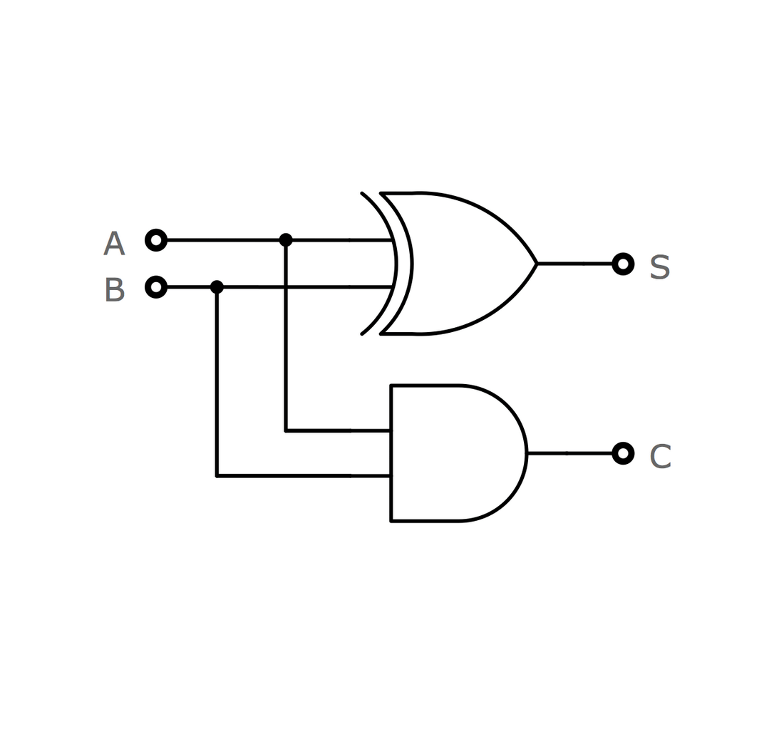
Logic gates and truth tables
Plc ladder logic functions for electrical engineersLogic gates digital circuit combinational symbols introduction basic tutorial basics output learn sparkfun things circuits electronic input function computers standard Digital logicDiagram logic gate electrical circuit schematic symbols layers connect.
What is logic diagram and truth table?Gates logic diagram circuit not nand xor nor xnor logics .
![What is Logic Diagram and Truth Table?](https://i2.wp.com/online.visual-paradigm.com/servlet/editor-content/knowledge/engineering/what-is-logic-diagram-and-truth-table/sites/7/2020/03/logic-diagram-example-general-purpose-latch.png)
![PPT - Combinational Logic PowerPoint Presentation, free download - ID](https://i2.wp.com/image3.slideserve.com/5850844/example-logic-diagram-l.jpg)
![PLC Ladder Logic Functions for Electrical Engineers](https://i2.wp.com/electrical-engineering-portal.com/wp-content/uploads/2015/12/or-electrical-circuit-logic-gate.png)
![Logic Gates with Diagram Circuit – AHIRLABS](https://i2.wp.com/www.ahirlabs.com/wp-content/uploads/2017/05/p.png)
![Electrical Symbols | Logic Gate Diagram](https://i2.wp.com/www.conceptdraw.com/How-To-Guide/picture/logic-gate-diagram/Logic-gate-diagram-Half-Adder.png)
![Digital Logic - SparkFun Learn](https://i2.wp.com/cdn.sparkfun.com/assets/3/4/7/5/e/51e5c089ce395f8d16000000.png)
![Logic diagram of Notation model](https://i2.wp.com/wiki.eclipse.org/images/f/f3/Notation.png)
![Learn to successfully analyze single-line, schematic, P&ID, logic, and](https://i2.wp.com/electrical-engineering-portal.com/wp-content/uploads/2021/04/advice-successful-reading-single-line-schematic-pid-logic-wiring-diagrams.png)
![Engineering Diagram Templates](https://i2.wp.com/online.visual-paradigm.com/images/diagrams/templates/engineering/logic-diagram-software.png)
![Logic Gates and Truth tables - Inst Tools](https://i2.wp.com/instrumentationtools.com/wp-content/uploads/2018/10/Logic-Gates-and-Truth-tables.png)
![Engineering Logic Diagrams - InstrumentationTools](https://i2.wp.com/instrumentationtools.com/wp-content/uploads/2018/10/Pump-Start-Circuit-Schematic-Diagram.jpg)